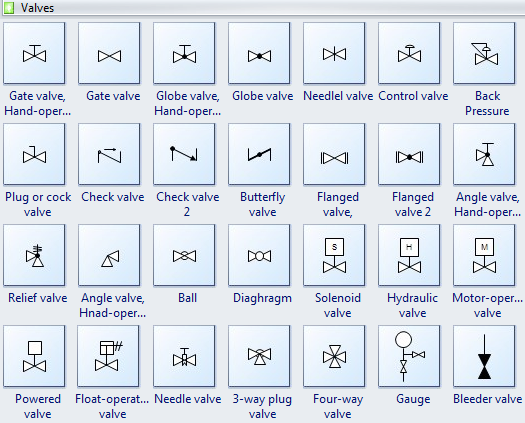
Flow Control Valves Diagram Valve Flow Control Hydraulic Dia
Control station and control valve in the process piping Flow control valve: definition, types, components & working principle Hydraulic flow control valves
Schematic diagram of the flow control valve | Download Scientific Diagram
Flow control valve function and diagram Pressure flow compensated regulator valves valve control circuit hydraulic Control valves flow hydraulic work animation valve diagram system mechanical wiring
Control flow valves valve hydraulic work types main
What is a flow control valve and what are the functions of flow controlFlow control valve hydraulic symbol valves system pressure compensated diagram parker way Flow control valvePool valve spa valves way ball system port diverter pools set simple spas repair diagram plumbing water basic manual actuated.
Piping design tips and guide : process flow diagram symbolsHydraulic circuit diagram ppt, animation Pressure compensated flow regulator valves • related fluid powerControl valve symbols.

Flow control valves
Flow control valve: definition, types, components & working principle[diagram] piping valve diagram Non-pressure-compensated valvesFlow control valves diagram types working uses pdf – artofit.
Valves flowValve symbols valves flow process diagram symbol gate instrumentation control piping engineering boiler pump mechanical plumbing standard drawing their pfd Valves principle engineeringlearnFlow control valves.

Flow control valve training
Hydraulic flow control valvesSchematic diagram of the flow control valve Principle engineeringlearnUnderstand flow control valves.
Zawór z regulacją przepływu 3 kluczowe informacjeValve schematic Flow control valves diagram, types, working & usesControl valve positioner circuit diagram.

Valve flow control hydraulic diagram pressure compensated parker operation valves bobcat two 31b permission reprinted hannifin showing figure auxiliary dcv
What are hydraulic flow control valves and how to testPressure compensated non valves flow control hydraulic schematic needle diagram troubleshooting Piping station processHydrastar flow control valve — 3/8in., model# f600s.
Valve flow control adjustable hydraulic valves f800s directional hydrastar model 2056 stl 2in 2057 item 8in northerntool hydraulics zoro quickFlow hydraulic control valve symbol valves test finotek generally classified Valves actuator positioner instrumentation functions principle instrumentationtools process breatherFlow control valves: diagram, types, working & uses [pdf].

Backpressure regulating valve valves pressure back schematic limiting spring loaded illustration inlet plunger side
Flow control hydraulic valves pressure compensated circuit symbology controlsSchematic diagram of flow/pressure valve control: (a) meter-out flow Valves understand fluidpowerjournalValve working principle globe plug labels basic.
Pressure-compensated valvesFlow control valves || toolts How flow control valves workFlow control valve diagram.

Flow control valves
Pressure compensated flow control schematic valves valve hydraulic diagram orifice fig .
.


![Flow Control Valves: Diagram, Types, Working & Uses [PDF]](https://i2.wp.com/www.theengineerspost.com/wp-content/uploads/2021/09/Flow-Control-Valves.jpg)


